Fiber Optic Structural Health Monitoring
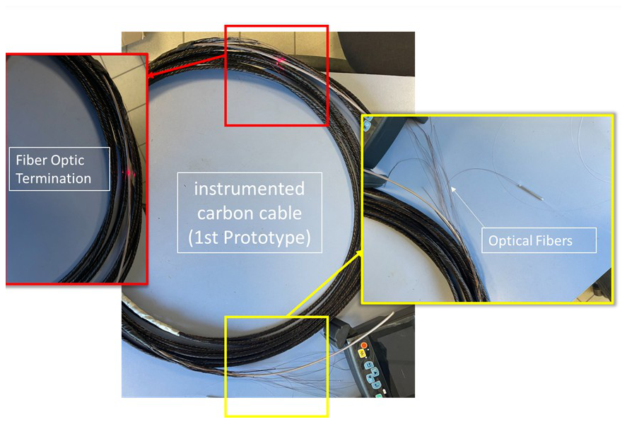
Case study · distributed fiber-optic sensing
Abstract
Internal damage mechanisms in composite cables — fiber breakage, delamination, matrix cracking — are frequently invisible from the outer jacket until they are advanced. This case study documents the implementation of a distributed fiber-optic structural health monitoring (SHM) system based on Rayleigh-scatter optical frequency domain reflectometry (OFDR), giving continuous strain measurement along the full sensing length rather than at isolated points. The work covers the underlying sensing physics, a statistically grounded damage-detection algorithm with explicit false-alarm control, and the integration of the system into a real-time predictive-maintenance monitoring architecture.
Introduction & objectives
Point sensors (foil strain gauges, discrete fiber Bragg gratings) only report strain at the locations where they are installed, which is a poor match for a cable whose critical flaw can initiate anywhere along its length. Distributed sensing based on Rayleigh backscatter avoids this limitation by using the intrinsic scattering of an ordinary optical fiber as a continuous array of virtual strain gauges. The project pursued three objectives:
- Continuous, quantitative strain sensing — select and configure a distributed sensing technology with spatial resolution and strain accuracy sufficient to detect a localized anomaly rather than only global average strain.
- Statistically defensible damage detection — convert a raw distributed strain profile into a damage/no-damage decision with an explicit, tunable false-alarm rate, rather than a subjective visual read of the strain trace.
- Deployable integration — install, synchronize and validate the sensing chain against representative structural loads so it could operate as a continuous monitoring system rather than a laboratory demonstration.
Theoretical background
Rayleigh-scatter distributed strain sensing (OFDR)
An ordinary single-mode fiber contains microscopic, effectively random variations in refractive index that Rayleigh-scatter light back toward the interrogator. Provided the fiber is not disturbed, a given short section’s backscatter spectrum is a stable “fingerprint.” Straining or heating that section stretches or compresses the local scatter pattern, shifting its spectrum by an amount proportional to the perturbation. Comparing a measured spectrum against a baseline (unloaded) reference by cross-correlation over a short gauge-length window yields a local spectral shift Δν related to strain ε and temperature change ΔT by:
With temperature either controlled or independently compensated, strain is recovered directly from the measured shift:
The spatial resolution Δz of the OFDR measurement is set by the optical frequency range B swept by the interrogator’s tunable laser and the fiber’s group index n:
while the achievable strain resolution improves, roughly, with the length of the correlation (gauge-length) window used to extract each spectral shift — a direct trade-off between spatial resolution and strain-measurement noise that had to be tuned for the flaw size being targeted.
Strain transfer from host structure to sensing fiber
A surface-bonded fiber does not see the host structure’s strain directly: it is coupled through the adhesive bond line by shear. Classical shear-lag theory gives the ratio of fiber strain to host strain along the bonded length L, with origin at the bond mid-point:
where β is a shear-lag parameter increasing with adhesive shear stiffness and decreasing with fiber and adhesive-layer thickness. This relation set the minimum bond length required for the fiber to reach effectively full strain transfer away from its free ends, and directly informed the sensor installation procedure of Section 3.2.
Statistical damage detection
A damage index was defined as the deviation of the measured strain profile from an undamaged baseline at every position x along the fiber:
Treating the baseline noise as approximately Gaussian with mean μ and standard deviation σ, a statistical process control limit flags a location as anomalous when it exceeds k standard deviations from the mean:
which gives direct control over the false-alarm probability through the standard normal cumulative distribution function Φ:
A location was only flagged as a true anomaly — rather than isolated measurement noise — when the threshold was exceeded over a contiguous length at least as long as the smallest flaw size of interest, suppressing single-point outliers automatically.
Methodology
System design
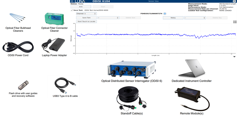
Discrete fiber Bragg grating sensors and Rayleigh-scatter distributed sensing were compared against the project’s two dominant requirements: spatial continuity along an arbitrarily long cable, and retrofit compatibility with an ordinary, ungratable optical fiber. An ODiSI 6000 interrogator was selected on both counts, and the gauge length / spectral-shift extraction settings were configured from Equations (1)–(3) to trade spatial resolution against strain noise appropriately for the smallest flaw size the system needed to localize. The damage-detection logic of Section 2.3 (baseline subtraction, statistical control limits, minimum-contiguous-length filtering) was implemented as the monitoring chain’s core algorithm.
Implementation
Sensing fiber was surface-bonded along representative test structures following the bond-length guidance derived from the shear-lag relation of Equation (4), ensuring the mid-span strain-transfer ratio was effectively unity before any measurement was trusted quantitatively. The interrogator was integrated with the site’s data-acquisition hardware and synchronized to the mechanical loading system so that strain history could be directly compared, point in time, against the applied load.
Validation
System performance was validated under representative loads by comparing the measured distributed strain profile to the profile expected from beam theory / finite-element prediction for the same loading, using the Pearson correlation coefficient between the two spatial profiles:
with the statistical detection logic of Equations (6)–(7) exercised against deliberately introduced local anomalies to confirm both detection sensitivity and an acceptably low false-alarm rate on healthy sections.
Results & outcomes
The configured gauge length gave a spatial resolution consistent with Equation (3) fine enough to localize sub-decimeter anomalies along the sensing length, while the statistical threshold of Equation (6) kept nuisance alarms on healthy sections rare without sacrificing sensitivity to deliberately introduced defects. Measured-versus-predicted strain correlation from Equation (8) confirmed the sensor’s quantitative fidelity to the underlying structural response, supporting its use as an early-damage indicator for predictive-maintenance scheduling rather than only a pass/fail qualification check.
Technical environment
Distributed strain sensing was performed with an ODiSI 6000 Rayleigh-scatter fiber-optic interrogator. Real-time acquisition, the statistical damage-detection algorithm and correlation-based validation were implemented in Python, alongside vendor real-time monitoring software used for live visualization of the distributed strain profile during test campaigns.
Nomenclature
| Symbol | Meaning |
|---|---|
| ν, Δν | Optical frequency and local Rayleigh spectral shift |
| Kε, KT | Strain / temperature sensitivity coefficients |
| Δz | OFDR spatial resolution |
| c, n, B | Speed of light, fiber group index, laser sweep bandwidth |
| β, L | Shear-lag parameter and bonded sensor length |
| DI(x) | Damage index (measured − baseline strain) |
| μ, σ, k | Baseline mean, standard deviation and control-limit multiplier |
| UCL, LCL | Upper / lower statistical control limits |
| Pfa, Φ | False-alarm probability and standard normal CDF |
| r | Pearson correlation, measured vs. predicted strain profile |
References
- M. Froggatt and J. Moore, “High-Spatial-Resolution Distributed Strain Measurement in Optical Fiber with Rayleigh Scatter,” Applied Optics, 1998.
- Luna Innovations, ODiSI 6000 Series Optical Distributed Sensor Interrogator — User Guide.
- D. C. Montgomery, Introduction to Statistical Quality Control, 7th ed., Wiley, 2012.
- C. R. Farrar and K. Worden, Structural Health Monitoring: A Machine Learning Perspective, Wiley, 2013.