Vibration Analysis & SHM for Predictive Maintenance
Case study · modal testing & predictive maintenance
Abstract
At Sigma (Clermont-Ferrand), this project characterized the dynamic behavior of structures and materials through experimental modal analysis, and used the resulting natural-frequency and damping baseline to deploy a vibration-based structural monitoring system for predictive maintenance. The work covers the theory of experimental modal identification, the use of resonant vibration testing to extract dynamic material properties, and the frequency-shift and modal-curvature indicators used to convert raw vibration data into a maintenance decision.
Introduction & objectives
A structure’s natural frequencies, damping and mode shapes are a direct fingerprint of its mass and stiffness distribution; damage or degradation that reduces local stiffness shifts that fingerprint in a measurable, repeatable way before the damage is otherwise visible. Exploiting this required first establishing a reliable experimental baseline, then extracting physically meaningful indicators from it, organized around three objectives:
- Modal identification — experimentally extract natural frequencies, damping ratios and mode shapes for the structures of interest with a repeatable test procedure.
- Material behavior characterization — use resonant vibration testing to infer dynamic material properties under different conditions, cross-checked against known beam-vibration theory.
- Monitoring deployment — translate the modal baseline into a deployed vibration-based monitoring system that flags meaningful change and supports predictive-maintenance scheduling.
Theoretical background
Modal analysis
A structure’s vibration response is governed by the general equation of motion
whose undamped free-vibration solutions define the natural frequencies ωn and mode shapes {φn} as the eigenvalues and eigenvectors of
Damping was extracted from the free-decay envelope using the logarithmic decrement δ between two peaks n cycles apart,
and, for forced-vibration testing, the single-degree-of-freedom frequency response function relates measured response to applied force in the frequency domain,
whose peak locates ωn and whose half-power bandwidth gives an independent damping-ratio estimate that was cross-checked against Equation (3). Experimentally identified mode shapes were compared against finite-element-predicted shapes using the Modal Assurance Criterion,
which returns 1 for perfectly correlated shapes and near 0 for unrelated ones, and was used to confirm that an experimentally identified mode and its numerical counterpart were in fact the same physical mode before comparing their frequencies.
Dynamic material properties from resonant vibration
For a uniform beam, Euler–Bernoulli theory relates the n-th natural frequency to the beam’s dynamic elastic modulus Edyn, cross-sectional properties (second moment of area I, cross-sectional area A), density ρ, span L and a mode-dependent constant λn set by the boundary conditions:
Inverting this relation from a measured resonant frequency gave a non-destructive estimate of dynamic modulus for different specimens and conditions, avoiding the need for a quasi-static mechanical test to compare material states.
Vibration-based damage indicators
The simplest damage indicator is the relative shift in a tracked natural frequency between a healthy and a current (potentially degraded) state,
which is sensitive to global stiffness loss but does not localize it. Where mode shapes (not only frequencies) were measured, a modal-curvature damage index — the change in the second spatial derivative of the mode shape between the healthy and current states — was used instead, since curvature change concentrates locally at the site of stiffness loss and is therefore able to localize damage rather than only detect its presence.
Methodology
Modal identification
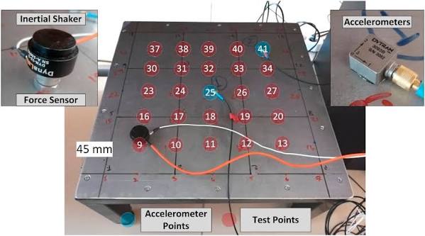
Structures were excited with an instrumented impact hammer and their response measured with accelerometers, and frequency response functions were computed and curve-fit to identify natural frequencies, damping ratios (Equation 3, cross-checked via the half-power bandwidth of Equation 4) and mode shapes. Identified mode shapes were correlated against finite-element predictions using the MAC of Equation (5) to confirm mode pairing before any frequency comparison was made.
Material behavior analysis
Resonant beam-vibration tests on representative specimens were used with Equation (6) to back out dynamic elastic modulus under different material states and loading histories, giving a fast, non-destructive way to track material property change without a full mechanical test campaign for every condition of interest.
System deployment
A baseline modal signature (natural frequencies and, where instrumented, mode shapes) was established for the monitored structure in its known-healthy state. Embedded sensors then tracked these quantities continuously, flagging a state change using the frequency-shift indicator of Equation (7) against a threshold set from the measurement repeatability observed during baseline characterization, with the modal-curvature indicator available where localization, not just detection, was required. Alarm thresholds and inspection triggers were set to balance false alarms against the cost of a missed early-stage degradation, directly informing predictive-maintenance scheduling.
Results & outcomes
Curve-fit natural frequencies and damping ratios from Equations (2)–(4) matched finite-element predictions closely enough, once mode pairing was confirmed with the MAC of Equation (5), to validate the numerical model against physical measurement. Dynamic modulus extracted via Equation (6) tracked known differences between material states consistently with expectations, confirming the resonant-vibration method as a viable non-destructive proxy for material condition. The deployed monitoring system’s frequency-shift threshold reliably distinguished normal operational variability from genuine state changes, supporting a shift from fixed-interval to condition-based maintenance scheduling.
Technical environment
Modal data acquisition and curve-fitting were performed in MATLAB / Python, with finite-element cross-checks in COMSOL / Ansys (multiphysics FEA). The deployed monitoring system used embedded sensors for continuous, in-service data collection.
Nomenclature
| Symbol | Meaning |
|---|---|
| [M], [K], [C] | Global mass, stiffness and damping matrices |
| ωn, fn, {φn} | Natural circular / cyclic frequency and mode shape |
| δ, ζ | Logarithmic decrement and damping ratio |
| H(ω) | Frequency response function |
| MAC | Modal Assurance Criterion |
| Edyn, I, A, ρ, L, λn | Dynamic modulus and beam section / mode properties |
| Δf/f | Relative natural-frequency shift damage indicator |
References
- D. J. Ewins, Modal Testing: Theory, Practice and Application, 2nd ed., Research Studies Press, 2000.
- R. J. Allemang and D. L. Brown, “A Correlation Coefficient for Modal Vector Analysis,” Proceedings IMAC, 1982.
- A. K. Pandey, M. Biswas and M. M. Samman, “Damage Detection from Changes in Curvature Mode Shapes,” Journal of Sound and Vibration, 1991.
- ASTM E1876, Standard Test Method for Dynamic Young’s Modulus by Impulse Excitation, ASTM International.